
Automated control for manual dial thermostats.
- Case
- 173.5 × 136.4 × 53.5 mm
- Link
- Bluetooth Low Energy
- Dial travel
- 180°
- Battery
- ≈ 1.7 years*
* Calculated: alkaline cells, 4 moves every day of the year.
01 · How it works
Your thermostat stays.Model 01 turns its dial.
Model 01 does not replace your thermostat. It takes the place of the snap-on cover and turns the dial shaft the way your hand turns the knob, so the thermostat still switches the heating itself. Press Move to ON and watch the drive turn the dial.
Face marks, end stop and pointer as measured on the real thermostat. Shapes simplified; sizes from the v6 drive.
- Dial travel
- 000°
- Motor shaft turns
- 0.00
- Motor half steps
- 0
- Motor time, s
- 0.0
Thermostat off
The orange pointer shows where your knob's pointer would point: OFF just short of LO, ON from straight up. The keys run a move 10 times faster than the motor does. A full move is 3.15 turns of the motor shaft: about 12,840 half steps (4,076 per turn, through the motor's 63.68 : 1 gearbox) at 2.0 ms each, 25.7 s. The thermostat switches on 140° past its LO stop, 120° of travel from OFF. OFF sits 20° short of the LO stop, so the drive never presses the dial against it.
- Step 01
Fit
The thermostat's snap-on cover comes off. Model 01 snaps onto the metal plate in its place, two side screws take up the play, and a sector pushes onto the dial shaft where the knob was.
- Step 02
Command
Your Raspberry Pi sends ON or OFF over Bluetooth Low Energy. The XIAO nRF52840 inside receives it and switches on the angle sensor.
- Step 03
Drive
The stepper motor turns the capstan. The cord turns the sector, and the dial shaft with it, 6.30 times slower: 3.15 motor turns move the dial 180°, in 25.7 s.
- Step 04
Confirm
The AS5600 reads the shaft's angle, and the motor stops at OFF or ON. If the dial does not move, the motor stops and the unit reports it.
- Step 05
Thermostat
At ON, the thermostat's own mechanism switches the heating, as it does when the knob is turned by hand. Model 01 then switches off everything except the radio.
02 · Introducing Model 01
No buttons. No screen.No lights. By design.
Model 01 holds every working part inside one faceted case: 45° corner clips, sides that angle in toward the wall, and a 3.0 mm shadow gap round the cover. Nothing to press, nothing to read, nothing lit. Your Raspberry Pi sends the command; Model 01 turns the dial. Pictures are path-traced renders of the CAD model.
- Battery access panelchange cells with the unit on the wall
- Grip indentsfive grooves for a fingertip hold
- Shadow gap3.0 mm wide, 2.6 mm deep, all round
- 45° corner clips16 mm, on all four corners
- Model tag01
- Facet markingEMBER THERMAL DRIVE TC-01
- EMBER wordmarkStop letterforms in a framed plate
Model 01 enclosure
173.5 × 136.4 × 53.5 mm · PLA · render of the CAD model
AFrom below left: the sides angle in toward the wall.
BRight side, with the facet marking.
CTop port: the thermostat plate's edge stays open to the room, as with the original cover.
DBottom port, matched to the top.
EAccess panel off: three AA cells, changed in place. Cells shown in a stand-in pocket.
FThree AA cells in series. Alkaline or NiMH.
GModel 01 rendered into a photo of the thermostat's wall. Composite image; the unit is in development.
HThe same wall from further back, above the light switch.
03 · Features
No more walkingto the dial.
Model 01 fits a line-voltage dial thermostat for electric in-floor heating and turns its dial to OFF or ON when your Raspberry Pi sends the command. The thermostat stays. The wiring stays. The dial turns on command.
- F-01
Direct-fit design
Replaces only the snap-on cover of an 859M dial thermostat. The metal plate and its two screws stay in place. No rewiring.
- F-02
Wireless command link
Bluetooth Low Energy from your Raspberry Pi to a Seeed XIAO nRF52840 inside the unit. Two commands: OFF and ON.
- F-03
Angle-sense feedback
An AS5600 magnetic sensor reads the dial shaft in steps of 0.088°. If the dial does not move while the motor runs, the motor stops and the unit reports it.
- F-04
3-cell power
Three AA cells. About 2.4 years per set at 4 moves a day, October to April (calculated). Change them with the unit on the wall.
- F-05
One-piece removal
Loosen two side screws and the whole unit pulls straight off: case, motor, drive and sensor together. Push the original knob back on and the thermostat works by hand.
- F-06
Mains-clear enclosure
No screw, contact, magnet or wire near the plate's openings to the mains-voltage parts. Solid plastic closes them off. The USB port faces down, out of sight.
- F-07
Fail-safe hold
If the cells run flat, the gearbox inside the motor holds the dial where it is, and the thermostat keeps regulating at that setting. No failure can leave the heater running without control.
- F-08
Early battery warning
The unit reports its battery voltage after every move. The Pi turns those readings into a percentage and warns before a move would fail: about two months ahead, in simulation.
- F-09
Field-serviceable
Motor replacement: two screws and one plug. M3 screws throughout.
04 · Inside Model 01 · cover off
Every part placed.Every wire routed.
Lift the cover and this is Model 01: battery bay, motor and capstan, cord-driven sector, angle sensor and controller. Each part is placed in the CAD model, every wire is routed with its length, and the build script reports any overlap.
- ULN2003 driver boarddrives the motor's four coils
- Battery bay v1three AA cells in series
- 28BYJ-48 motor and capstan v642 mm left of the dial shaft
- Seeed XIAO nRF52840controller and radio; USB-C faces down

- Side screwone each side, pressing a tongue onto the plate's edge
- AS5600 angle sensor2.0 mm in front of a magnet in the sector's hub
- Sector v6fixed to the dial shaft; the cord runs round its rim
- Wiringevery wire routed with its length
Model 01 · internals
From the CAD model · ULN2003 and XIAO sizes estimated
05 · Capstan drive · 6.30 : 1
Capstan drive.6.30 : 1 reduction.
A grooved capstan on the motor shaft winds a 0.50 mm braided cord. The cord's ends are anchored to a sector on the dial shaft. The cord's centre runs at 5.66 mm from the motor shaft and 35.66 mm from the dial shaft. Result: the dial turns 6.30 times slower than the motor shaft, with 6.30 times its torque, less friction, over 180° of travel. The interactive model is in section 01.
- Twin-sled tensioninga screw pulls each sled to take up slack
- Cord clampa screw locks each cord end
- Level rim entrya round hole where the cord enters the rim

- Capstangrooved for the 0.50 mm cord, with spare turns
- Cord face35.41 mm radius between two lips; cord centre at 35.66
- Sector180° of travel
- Push-fit hubD hole for the dial shaft
Capstan drive v6
Sent to the printer 2026-10-16 · fitting next
- v1:
- The cord slid off the edge of the sector: its face had no spare width.
- v2:
- Lips on the sector kept it there, but the cord slid along the capstan, piled up at one end and came off.
- v3:
- A lip at each end of the capstan.
- v4:
- A sector for the wall unit, whose D hole takes the whole D part of the dial shaft. Not printed.
- v5:
- Each cord end tightened by a screw-driven sled. Fitted on 2026-10-15: the sleds' 3.6 mm of take-up left about 5 mm of slack.
- v6:
- A capstan groove sized for the 0.50 mm cord, with spare turns, and a screw clamp for each cord end. Sent to the printer on 2026-10-16; not yet fitted.
06 · Power system
Three AA cells.No charger. No regulator.
Model 01 runs straight from three AA cells: no charger, no regulator, no wall adapter. Between moves it switches off the motor coils and the angle sensor and keeps only the radio on, ready for the Pi's next command. Cells flat? The motor's gearbox holds the dial where it was, and the thermostat keeps regulating at that setting.
- Mounting tabone of three posts
- Keyed + contacta reversed cell cannot touch it

- ULN2003 driverbehind the bay
- Access panel screw boss
- 3 × AA in seriesabout 4.8 V new, alkaline
- Isolated contact pocketsPLA between pieces at different voltages
Battery bay v1
Modelled 2026-10-16 from estimates · not printed
- Cells:
- 3 × AA, alkaline or NiMH
- Voltage:
- about 4.8 V with new alkaline cells
- Regulator:
- none
- One move:
- 0.75 mAh calculated
- Between moves:
- 20 µA estimate
- Usable charge:
- 81 % of an alkaline cell, to the motor's 3.3 V cutoff
- Cell change:
- unit stays on the wall
2.4years
864 days at 4 moves a day, October to April
- Charge on a day with moves
- 3.7 mAh
- Share taken by the motor
- 81 %
Choose a bar. Calculated by battery_model.py from Energizer's published curves for the E91 cell; not yet measured on the real unit.
07 · Circuit
Three modules.Fifteen wires.
One controller, one motor driver, one angle sensor, thirteen solder joints. The XIAO drives the motor through the ULN2003 and reads the AS5600 over I2C. The sensor draws power from two XIAO pins only while it reads, and motor current returns straight to the cells, never across the controller board.
Power
- Battery +
- XIAO BAT+ soldered
- Battery +
- ULN2003 + socket
- Battery −
- XIAO BAT− soldered
- Battery −
- ULN2003 − socket
Angle sensor
- XIAO D0 + D1
- AS5600 VCC socket
- XIAO D4
- AS5600 SDA socket
- XIAO D5
- AS5600 SCL socket
- XIAO GND
- AS5600 GND socket
- AS5600 GND
- AS5600 DIR soldered
Motor
- XIAO D7 to D10
- ULN2003 IN1 to IN4 jumpers
- Motor plug
- ULN2003 socket plug
Spare pins: D2 · D3 · D6
Take one cell out before connecting USB
The battery pads also feed the XIAO's lithium charger. With USB connected it would try to charge the AA cells, which can make them leak.
- Pad limit:
- every part on the XIAO's battery pads is rated for at least 6 V; three new alkaline cells give about 4.8 V. Four cells (about 6.4 V) would be over it.
- Routing:
- the sensor wires leave along the XIAO's USB-C end and the motor wires from the top of the other row, so the two groups do not cross.
- Wire stock:
- female-to-female jumpers, cut in half where a wire has a socket at one end only.
08 · Design history
Thirteen versionsin one day.
The Model 01 case went through thirteen versions on 15 October 2026. Each one was built by its own script, saved as its own STEP file and reviewed in Autodesk Fusion. Verdicts are the ones given at the time; a lit lamp marks each version that was liked or carried forward.
- v1
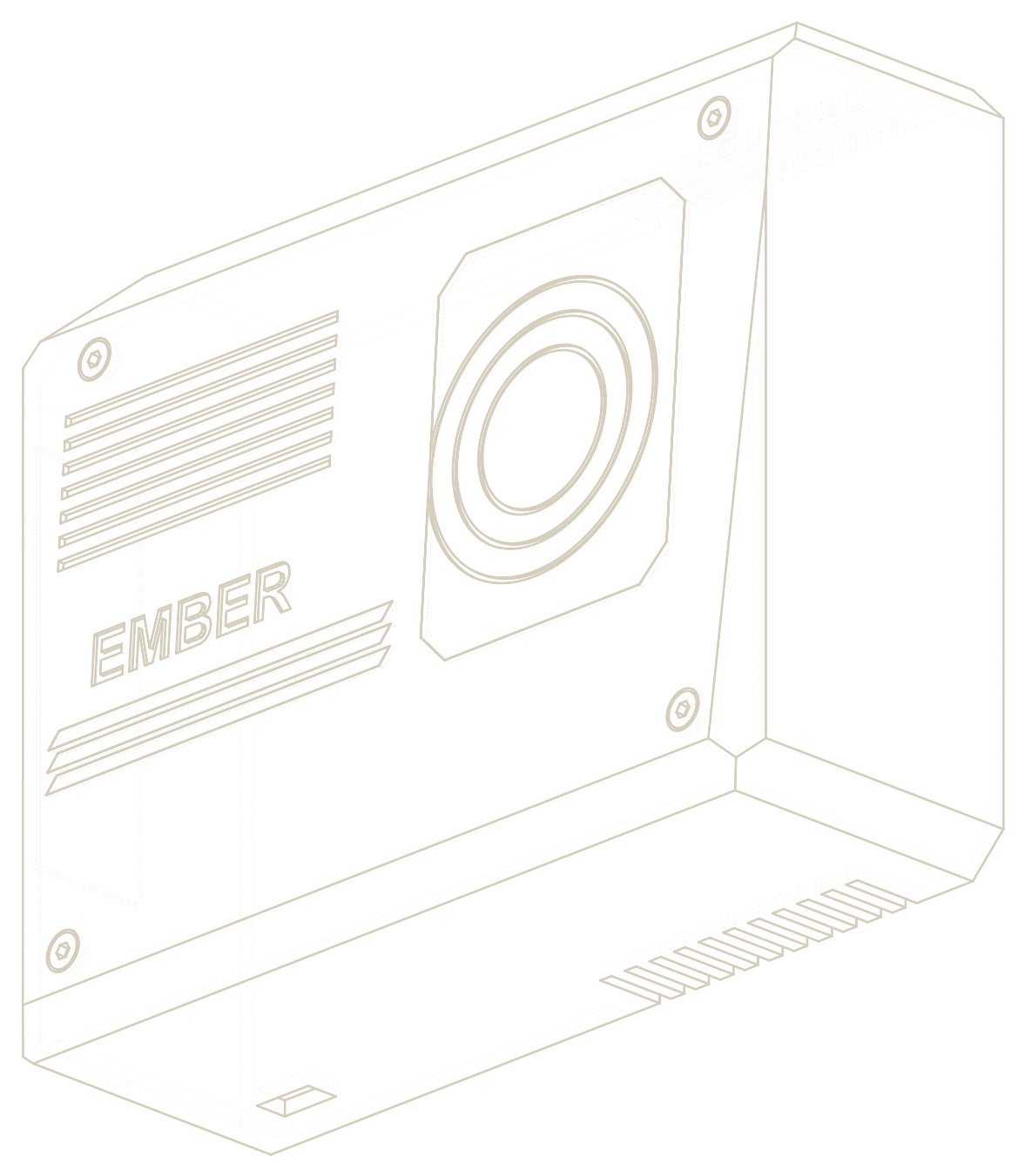
One box: slanted front, three colour stripes, a grille and a ring panel over the dial.
Verdict: too much like the 1980s, not enough futurism.
- v2
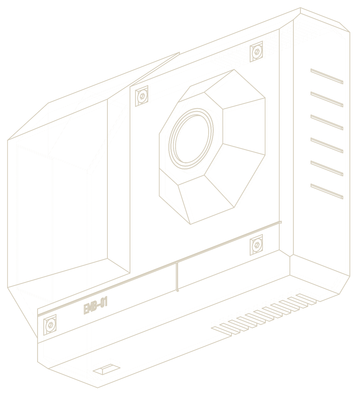
Separate raised forms: a battery pod and an eight-sided dial pod.
Verdict: not reviewed; reference images came instead.
- v3
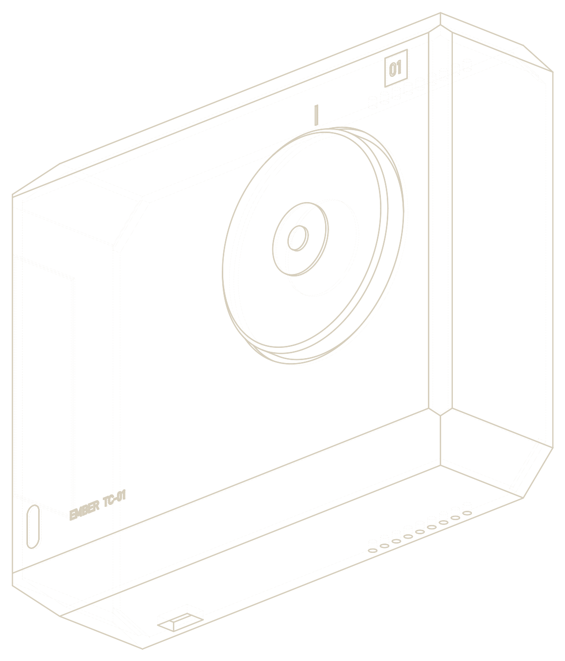
A flat cover in a deeper base, a large plain disc over the dial, round vent holes.
Verdict: not interesting enough; wanted interesting edges and sides that angle in.
- v4
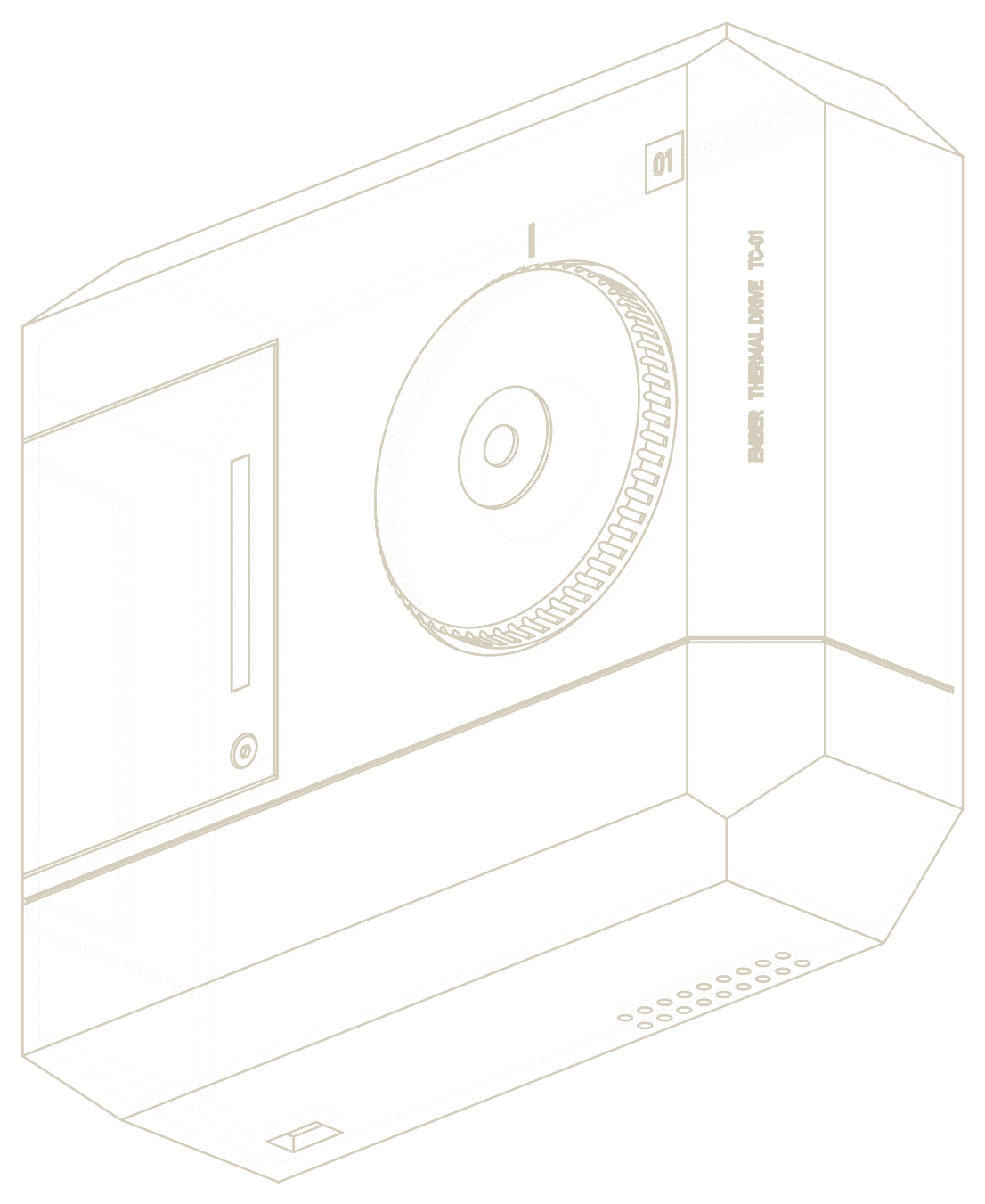
The sides angle in toward the wall; the front edges are cut by different amounts; an L-shaped battery cover.
Verdict: liked; saved as a favourite.
- v5
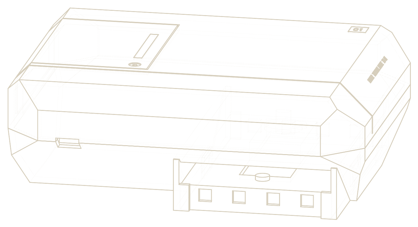
No disc. Top and bottom angle in steeply, leaving the plate's edges open to the room. Seen from below.
Verdict: interesting, but the angle is too steep and goes too far in.
- v6
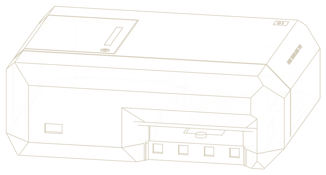
Flat top and bottom, with a port over each of the plate's edges. Seen from below.
Verdict: loved; saved as a favourite.
- v7
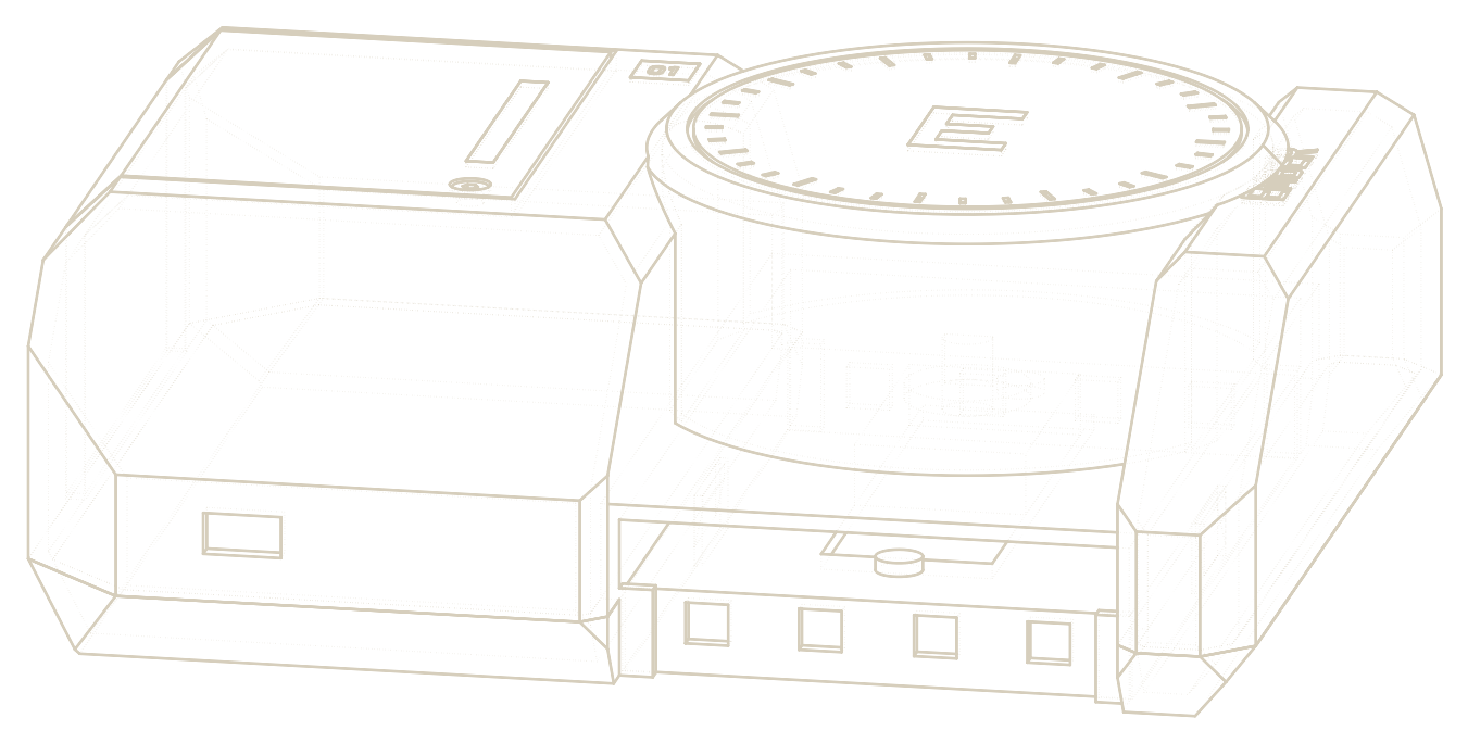
Three tries at a new direction: asymmetric cuts, a tower and pod, then a hull with a fin. Seen from below.
Verdict: still too close to the earlier designs.
- v6.1 – v6.2
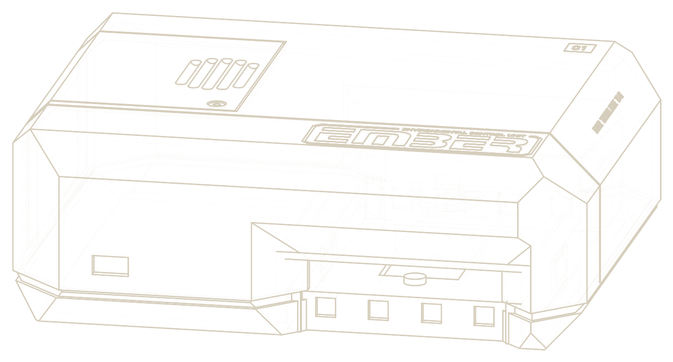
Back to v6: EMBER on the front, finger indents, an open gap where cover meets base; then the Stop letters in a frame.
Verdict: the design to go with.
- v6.3 – v6.5
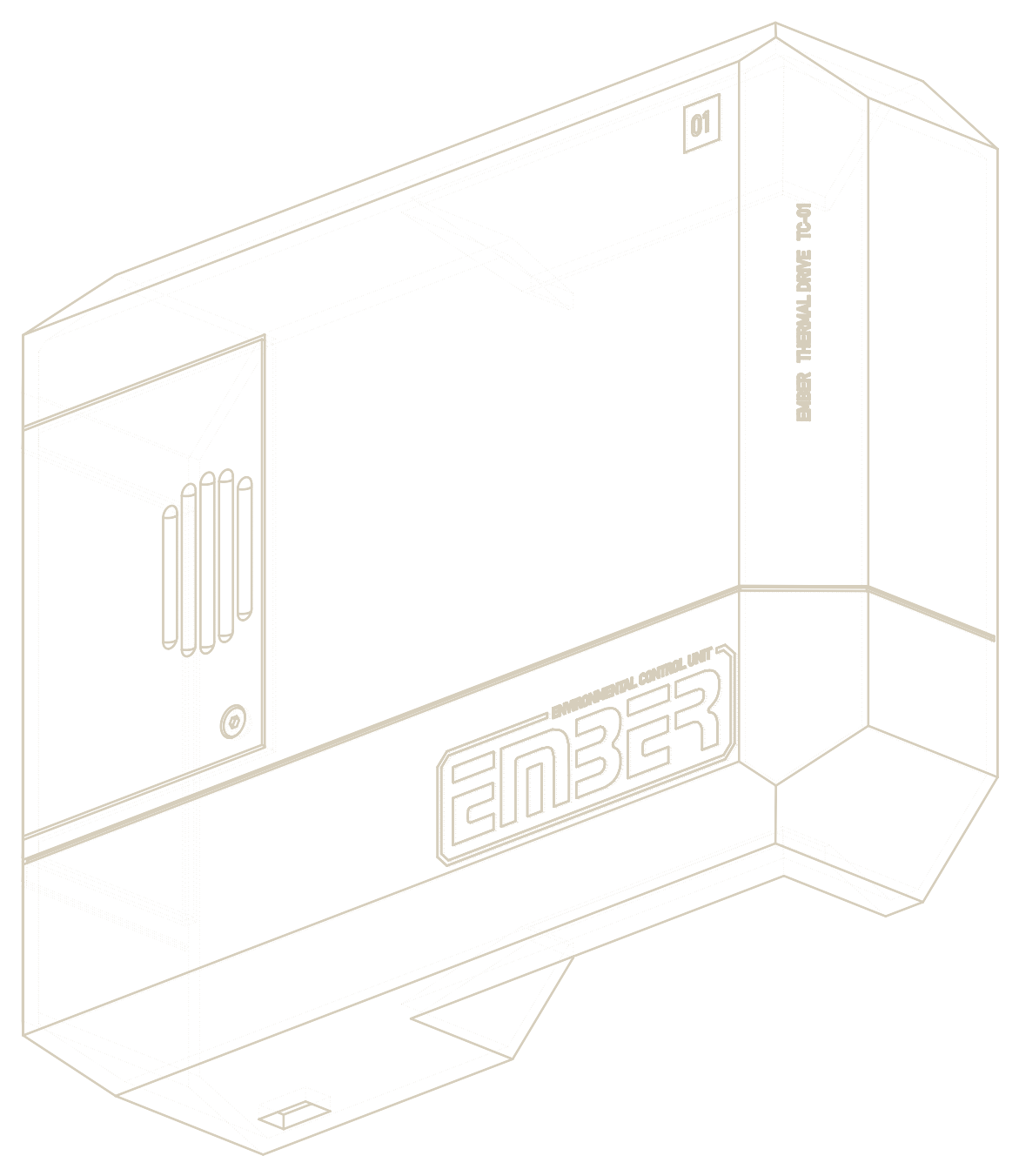
Fitted to the thermostat as measured with calipers; side screws; the same 16 mm clip on all four corners.
Verdict: looks good; wanted the screws on opposite sides.
- v6.6
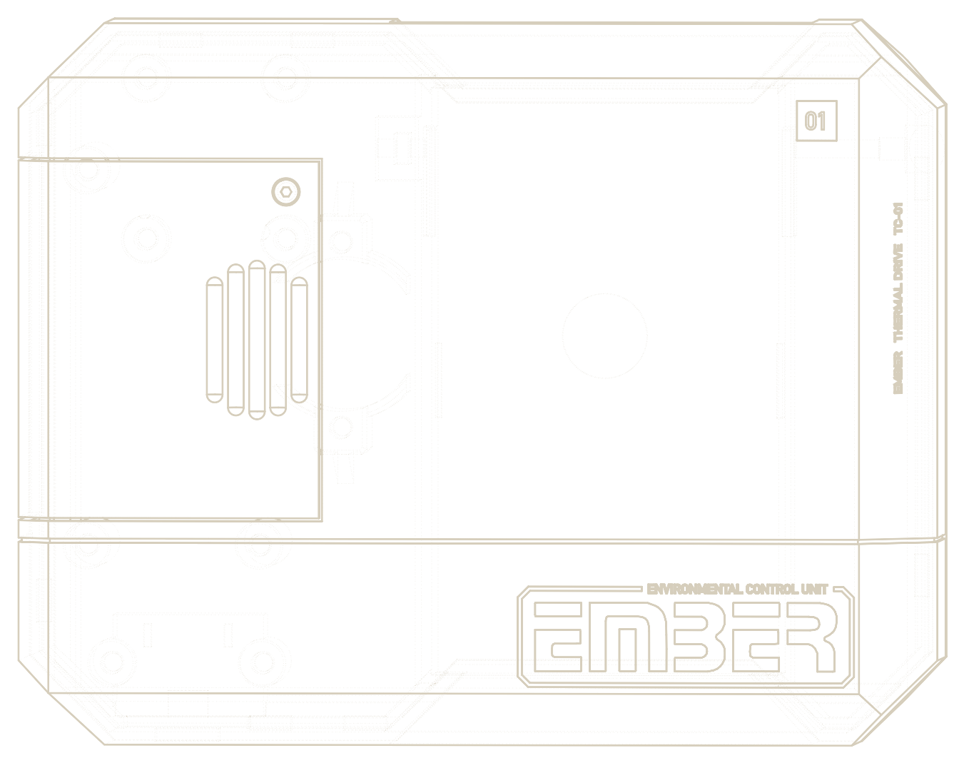
One side screw each side, directly opposite; a lip and a 3.0 mm gap all round. Changed in place from here on.
Verdict: right, and moving in the direction wanted.
09 · Technical data
Technical data.Model 01.
Every figure is marked with its source: design (the CAD model), calculated, datasheet, or estimate.
- Case:
- 173.5 × 136.4 × 53.5 mm; 157.5 × 122.4 mm on the wall design
- Fits:
- 859M line-voltage dial thermostat, in place of its snap-on cover design
- Mounting:
- on the thermostat's metal plate; two M3 side screws press plastic tongues onto its edges design
- Motor:
- 28BYJ-48 stepper, ULN2003 driver board datasheet
- Drive:
- capstan and sector, 0.50 mm braided cord (85 lb), ratio 6.30 : 1 design
- Dial travel:
- 180° from OFF; OFF is 20° short of the LO stop design
- One move:
- 3.15 motor shaft turns: about 12,840 half steps, 25.7 s at 2.0 ms per half step calculated
- Controller:
- Seeed XIAO nRF52840 datasheet
- Radio:
- Bluetooth Low Energy, commands from a Raspberry Pi design
- Angle sensor:
- AS5600 magnetic, 12-bit: 0.088° per count datasheet
- Power:
- 3 × AA, alkaline or NiMH, about 4.8 V with new alkaline cells datasheet
- Charge per move:
- 0.75 mAh on average calculated
- Between moves:
- 20 µA estimate
- Battery life:
- 2.4 years at 4 moves a day, October to April; 1.7 years at 4 moves every day (alkaline) calculated
- Material:
- PLA, printed on a Bambu Lab P1S with a 0.4 mm nozzle design
- Fasteners:
- M3 screws into brass heat-set inserts, 5 mm across, 4 mm long design
- Units:
- one to three to be built plan
10 · Development status
Development status.17 October 2026.
Model 01 is in development. Lit lamp: done. Half-lit: in progress. Dark: not started or not tested.
- Motor on the deskESP32 and ULN2003 board: the motor turned both ways on 2026-10-13.
- Cord sleds v5Printed and fitted on 2026-10-15.
- Capstan v6 and sector v6Sent to the printer on 2026-10-16; not yet fitted.
- Wall case v6.6Designed and fitted to the measured thermostat; not printed. The cover's fastening is not designed.
- Battery bay v1Modelled from estimates; waiting for caliper values of a cell and the contacts.
- WiringPlanned and routed in the model with every wire's length; not built.
- Motor torque on three AA cellsNot tested on the real dial.
- Battery lifeCalculated; not measured.